
The beginning
As a first post I’ll start with the very first work I’ve been doing in DIY electronics in a while (say, > 10 years), which is restoring a long forgotten ZX 81 I’ve been collecting in my museum (say, cellar), like, forever.
I’ve also owned the manuals, and I remember when I was eager to learn new programming languages I’ve always promised myself I would have learned the BASIC from these manuals, and give it a go. I never did. So, the least I could do was to make it work back again.
Note: Unfortunately, this is a “post mortem” post, as I didn’t document too much during the working process. Back then (~Sep 2025) I was not thinking about blog posting. The ZX81 is now already sold. Photos are as they go.
What seems to be the problem?
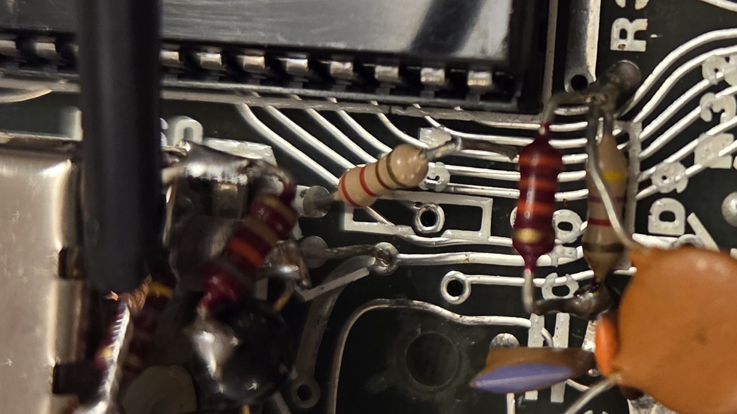
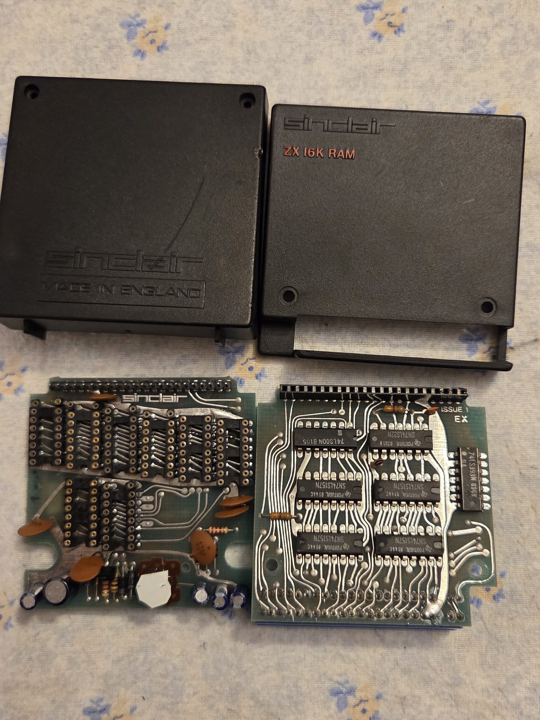
The computer is an Issue 1 from 1981, possibly made up from a kit as every IC was socketed. Back then you would buy an already mounted computer, or a DIY kit, to solder it yourself, for a cheaper price.
There have been some mods in between to:
- A little 3.5mm mono jack of unknown signal – I’ll get back to this later on
- Some additional caps+resistors attached in an area near the mic input
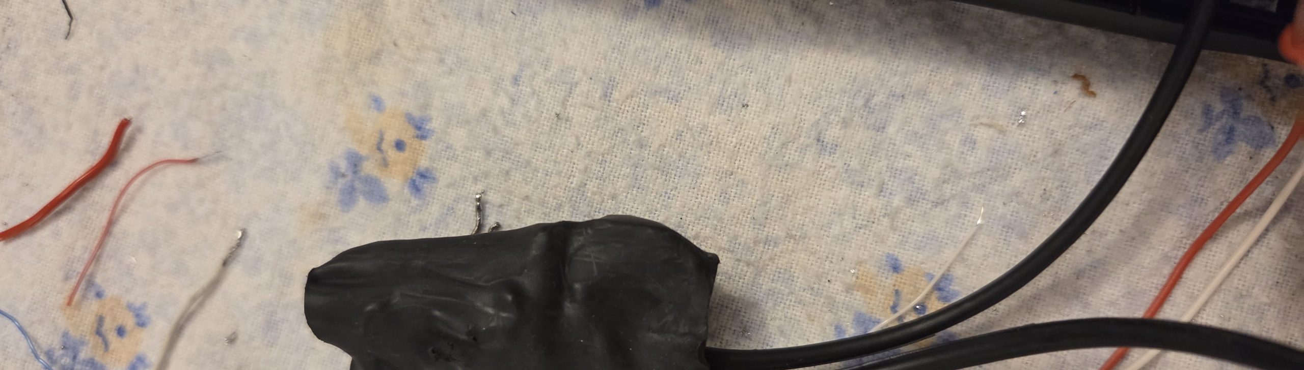
- A buzzer connected to a 74LS30 8-input NAND IC, connected to part of the keyboard connector
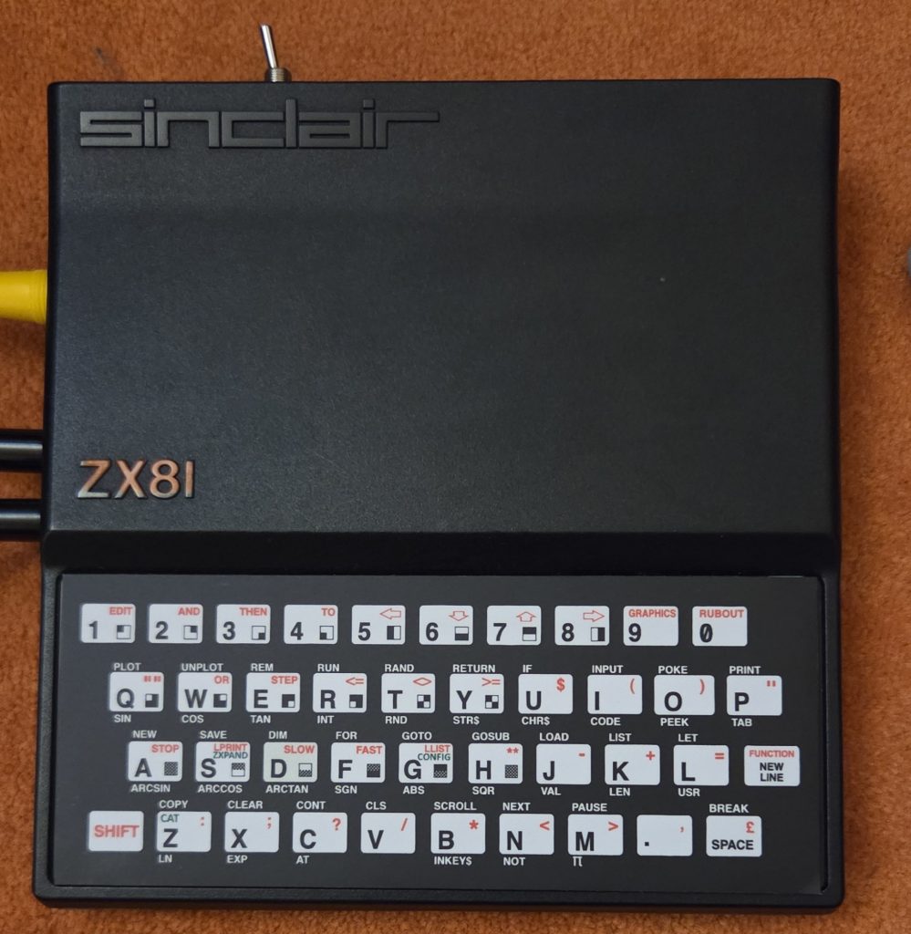
By turning it on my Very-CRT™ Sony TV through RF (UHF 36, 590-598 MHz in Europe, but my TV was locking on 600 Mhz) I could at least see the remarkably “we’re good to go”, which was just a (very dark and blunt):
K
Typing on the keyboard was working on some keys, but not all of them. But as the screen was good the overall hardware confirmed ok. Which was a big step ahead.
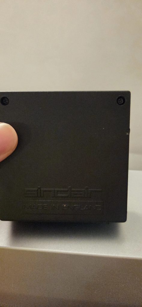
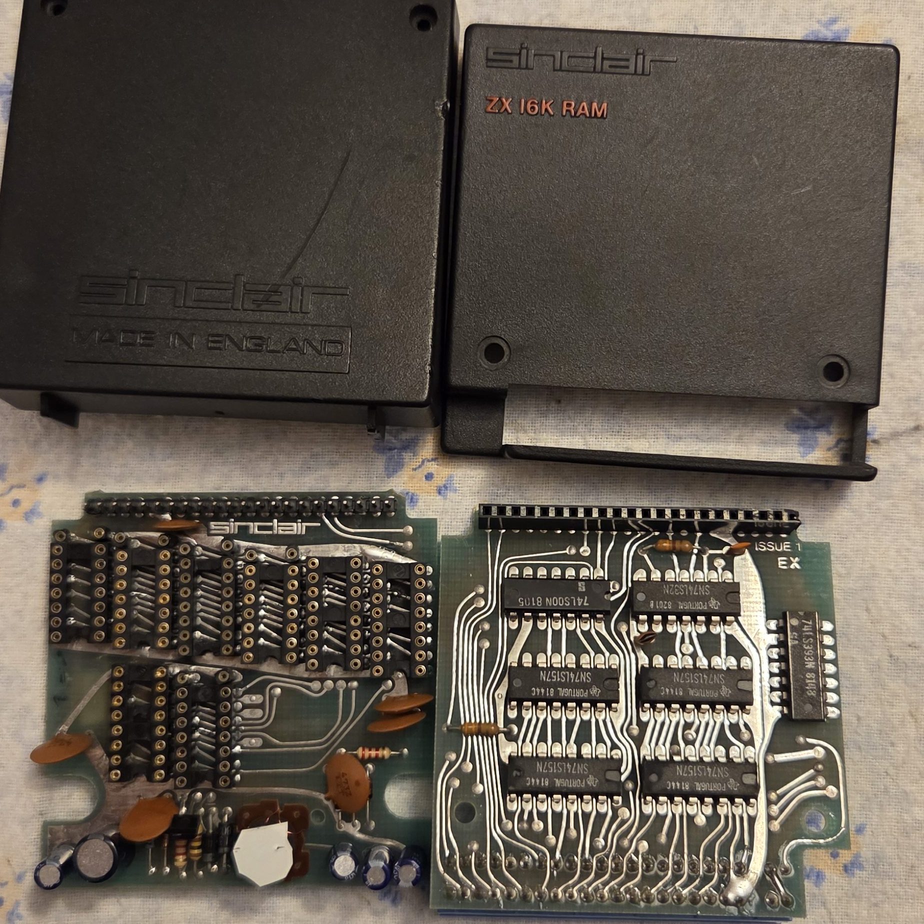
Wait, Did I mention I also had it’s way-big-for-the-time (and maybe worth an investment by these times of RAM shortage :> ) 16K memory pack (called Sinclair ZX 16K RAM)? I gave it a try, and it was a NOGO, with random static lines over the screen.
Doctor Herris, do you concour?
By “reverse engineering” (Google) I found the mini jack to be an attempt to get Composite video instead of the (I’d say pretty) bad RF signal out of the little box – it was just a shielded cable straight off an added NPN transistor. Note:The computer had no audio anyway, but back in 1981 TVs didn’t have any kind of input other than RF, so Sinclair adapted to the de-facto technology. But the thing is this little box was an Issue 1, which means it was running with a very first cheap model of ULA (Uncommitted Logic Array), model Ferranti ULA2C184E, which didn’t have the “back porch” signal to be amplified to get a valid Composite signal. So, the mod was an attempt, but rather a blind one, and it was left there forever be. With the following motherboards, a different ULA had been used, which allowed for a simpler composite mod, which required just a NPN transistor.
The buzzer was probably an attempt to replicate the buzzing known from Sinclair ZX80 and Spectrum when a key was struck on the keyboard. Call it feedback tactile/sound feedback on a membrane based keyboard, which didn’t give you any glimpse whether it actually got the hit or not. It didn’t work anyway, possibly the buzzer was cooked.
As for the RAM pack, the result suggested to me RAMs were faulty, even though I was hopeful for something better.
Also, after opening it, it became pretty clear the keyboard had its lines oxidated.
Bring it on
By now I had found what I should have been doing, which was:
- Try and mod for a composite video output even with the early ULA model present
- Possibly restore the buzzer
- Check on possibly additional mods to be done
- Check on the RAM pack
- Recap for safety both the mobo, and the PSU
- Check on the additional resistor + capacitor on the mic line
The whole job included cleaning with contact cleaner and IPA, of course, and then testing.
Some time after that…
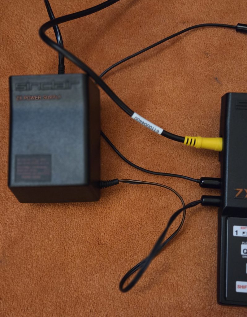
In the end the amount of work got a little longer, and included also removing the original 7805 linear regulator, which was HEATING way too much. Same goes for the ULA, and the EPROM. The Z80 CPU was also affected, but to a lesser degree. So I put a buck converter [1] which worked just great and fine, and some copper heat sinks on top of the ICs with new thermal pads. The buck converter was wrapped in heat shrink to avoid any shorts.
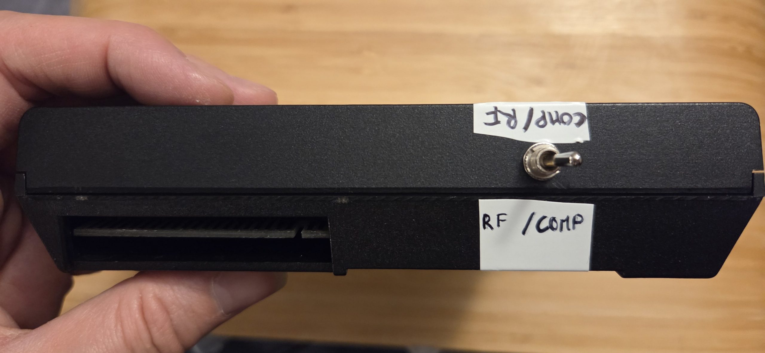
The Composite video mod was a simple one to be done, and included a NE555. The [2] and [3] are detailing out very well and fine how to do that. Since there was already a hole in the case I decided to put a DPDT switch and let the user choose between RF and Composite. Of course I’ve used shielded cables for signal carryng.
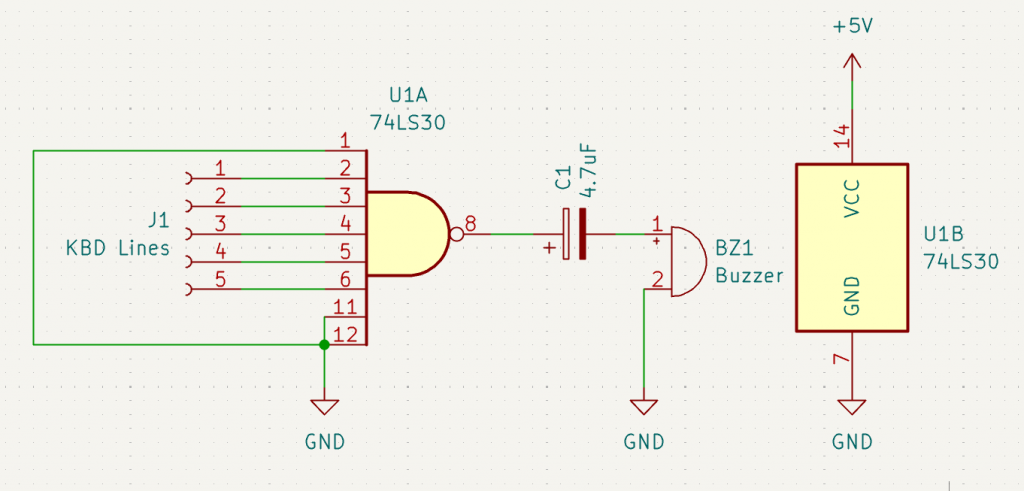
As for the buzzer: I didn’t have any passive spare buzzer available, and I just got rid of it. Though, I’m sharing the schematic as it was, as I found no reference of this mod across Sinclair community. Please note that I didn’t test it.
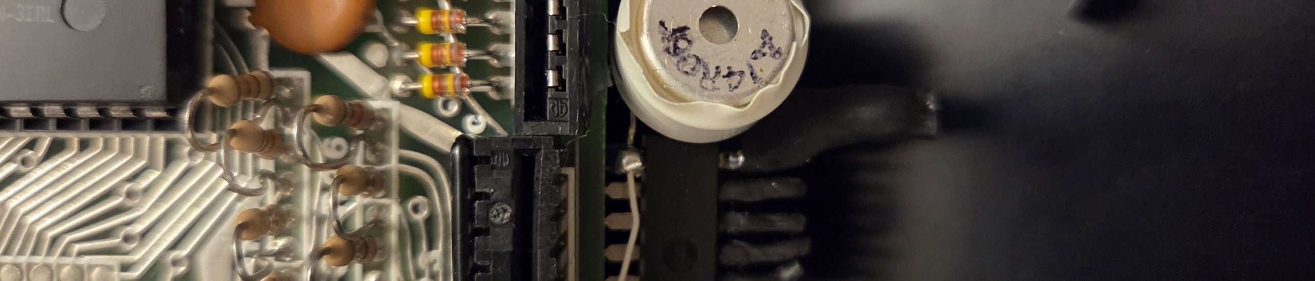
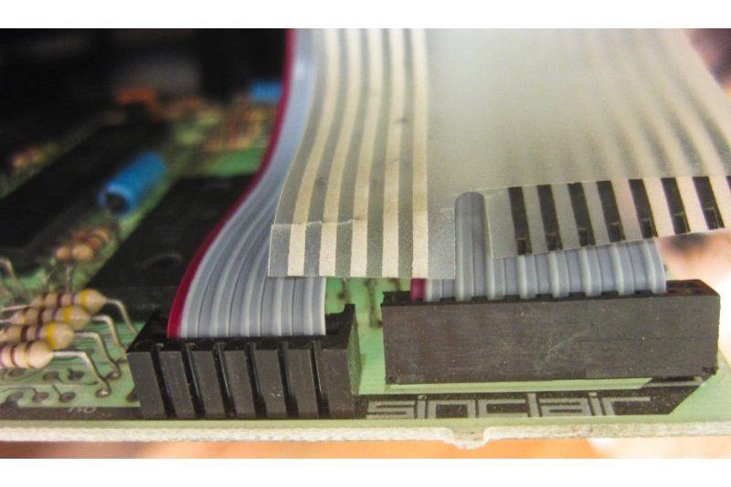
The keyboard! Ah. I’ve tried to salvage it by cleaning out the oxidation, but the job was impossible. Basically Sinclair used a cheap plastic with silver paint lines onto it to make it happen. Guess what, silver oxides, and plastic gets harder. So the plastic broke in between, and my copper pen was too wide anyway. See the comparison picture here. The plastic ones are the original.
I’ve decided (forced to?) to buy a new one, and I found [4] which is tactile SMDs and not just a membrane [4]. I highly recommend it.
The PSU has been recapped and the mobo as well, although I didn’t really feel the need of that anyway, better be sure than safe.
Along my research and restoration I discovered that back in the day ANYONE hated the ZX RAM Pack because the connector was so unstable, and the computer would just freeze in between if the connection was poor. So I’ve also cleaned that, and put some new lead to it – very gently, solder, then wipe the excess. It made a better stable connection with the RAM pack. Which I also fixed, see the next section.
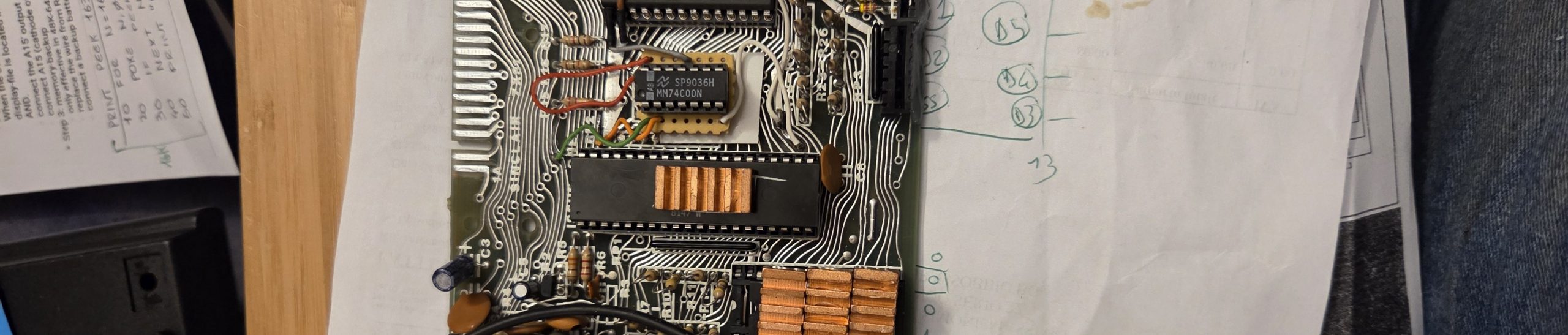
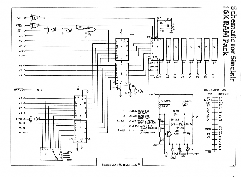
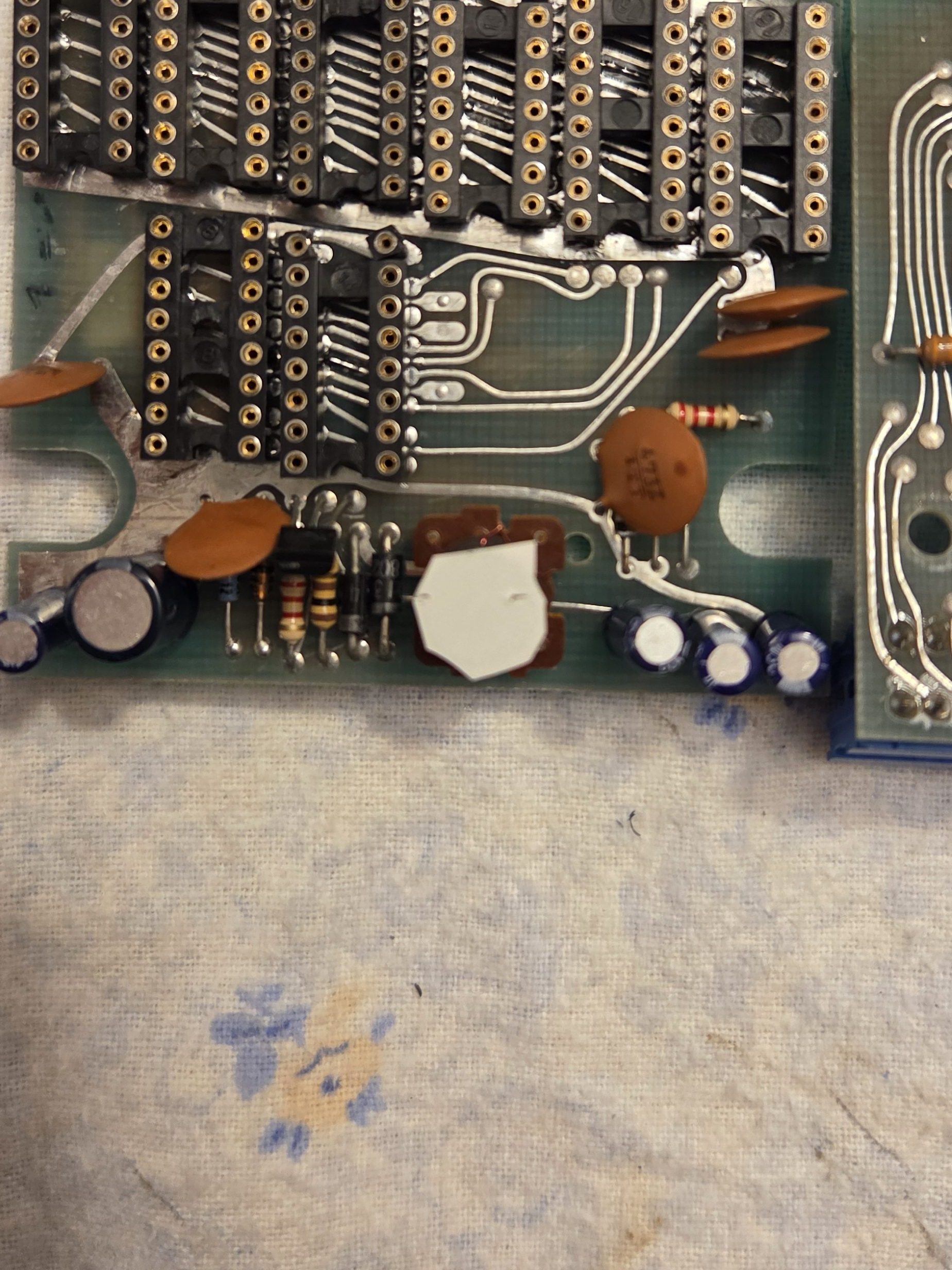
The RAM Pack itself was a no-brainer. The RAM chips were faulty. No cleaning of the sockets would help. The pack used 4116 200ns memories which needed multiple voltages (+5V , -5V, +12V). The thing is the ZX81 only provided a steady +5V through its linear 7805 regulator. So Sinclair provided. They put a discrete regulator (inductor) into the RAM pack, which would have picked up the +9V filtered unregulated voltage from the PSU to get -5V and +12V. Sick. See the [5] schematic.
Someone on the internet wants to get rid of the “pseudo-switching” regulation and install 4164 memories instead, which only require +5V voltage. But I wanted to stay legacy, and bought 8 x 4116, recapped it for good, and removed that embarrassing wire cable going through the 2 PCBs (yes, the RAM pack was made by 2 x 2 layers PCBs) with a more solid pin header row – got inspired by [6]. Of course I’ve also socketed all of them to avoid future chaos.
It was now time for testing the RAM Pack, which provided the right value. I don’t have a photo of that, but the program to test test – it took me a while to find a reliable one – is as follows:
10 FOR N=16640 TO 65536 STEP 256
20 POKE N,0
30 IF PEEK N<>0 THEN GOTO 50
40 NEXT N
50 PRINT "MEMORY SIZE ";(N/1024)-16;"K"
NOW THE FUN PART
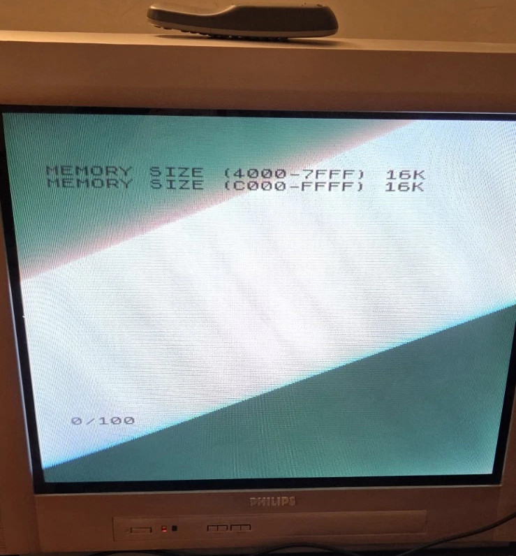
As it turned out, there was more juice to it. The ZX81 could be modded to include INTERNAL 16K or 32K RAM [7]. BOI.
I immediately sourced a 62256 32K x 8 memory and put it all together. In the process I found the original 4118 1K RAM had oxidized pins, which I cleaned.
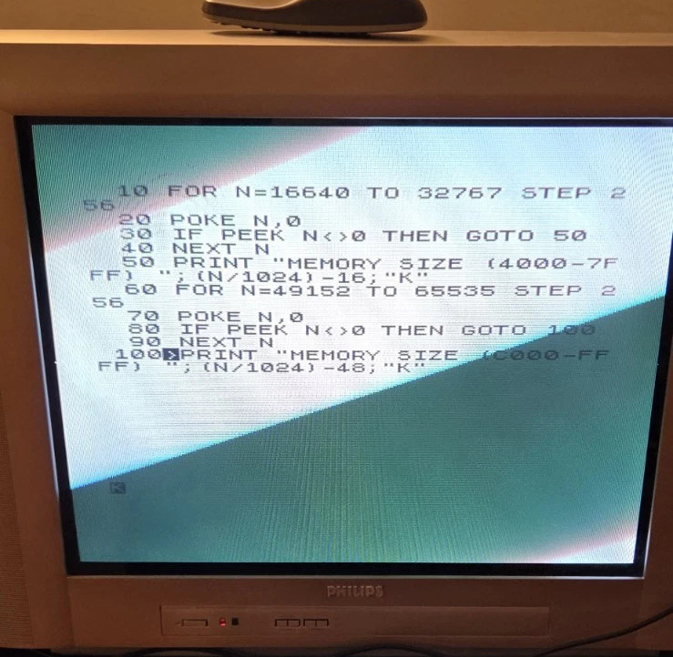
To test the 32K RAM (lower and upper 16Ks) one would need to run the following program instead:
10 FOR N=16640 TO 32767 STEP 256
20 POKE N,0
30 IF PEEK N<>0 THEN GOTO 50
40 NEXT N
50 PRINT "MEMORY SIZE (4000-7FFF) ";(N/1024)-16;"K"
60 FOR N=49152 TO 65535 STEP 256
70 POKE N,0
80 IF PEEK N<>0 THEN GOTO 100
90 NEXT N
100 PRINT "MEMORY SIZE (C000-FFFF) ";(N/1024)-48;"K"
IT. COULD. WORK!
Conclusion
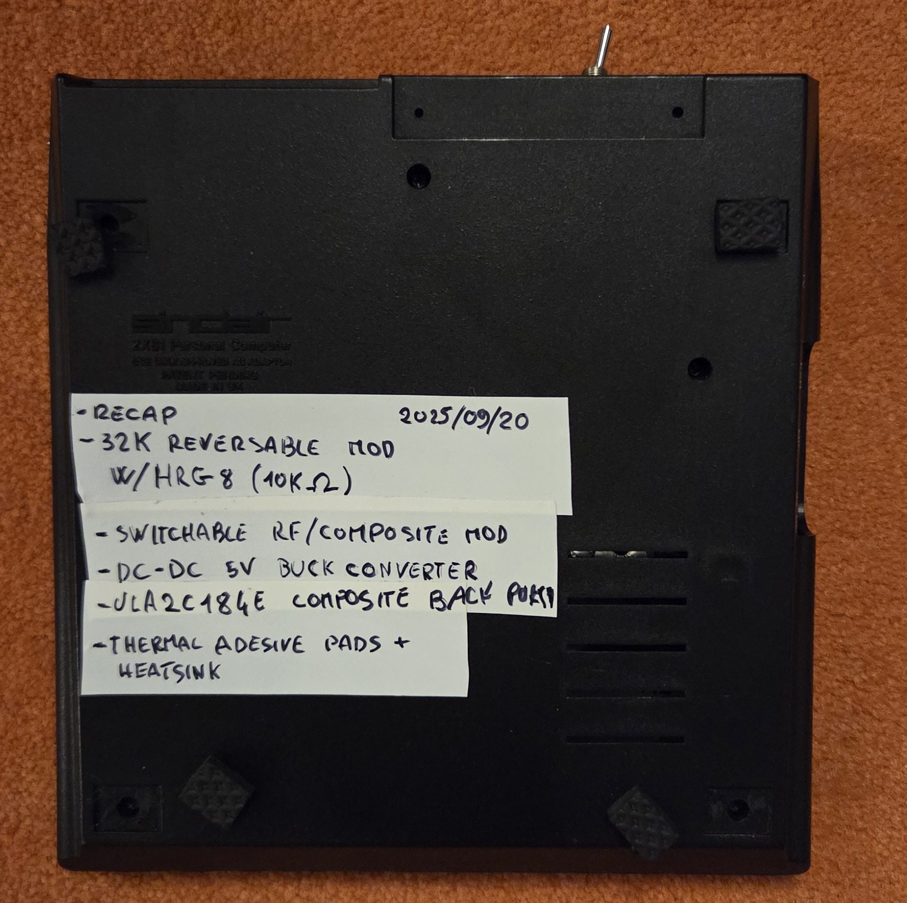
This was a funny project for me and a nice one to warm up after so many years of long forgotten modding/repairing. Here’s the list of what’ve been done in the end:
- Fully recapped
- Overall contact cleaning, especially with sockets
- Composite back porch NE555 signal “generation”
- Reversible Composite mod with Composite/RF switch (shielded cables)
- 32K RAM internal mod with 62256 32K x 8 RAM (w/HRG8 enablement) – socketed and reversible
- DC-DC 5V Buck Converter replacing the genuine 7805 linear voltage regulator
- Thermal adhesive pads with heatsink over ULA, ROM, and Z80
- New tactile keyboard as the original was totally faulty, unfortunately (inner vias where non-conducting)
- The PSU has also been recapped.
- The RAM Pack was refurbished with new 4116s, recapped, and socketed
The really hard thing was to keep it all within – the case is very thin. In the end I managed anyway.
Links
[1] https://amzn.eu/d/19fdxFX
[2] http://zx.zigg.net/misc-projects/?ref=blog.codesurfer.dev
[3] http://zx.zigg.net/misc-projects/ZX81_Video_Conditioning.pdf
[4] https://www.ginger-electronic.com/en/retro-computer/24-40-zx8-kdlx-keyboard-for-sinclair-zx81-and-zx80.html#/26-model-zx81
[5] https://www.retroisle.com/sinclair/zx81/Technical/Hardware/16KRamPackSchematics.php
[6] https://levosretrocomputerprojects.co.uk/zx81-ram-pack-issue-1-4164-update
[7] https://k1.spdns.de/Vintage/Sinclair/80/Doityourself/Internal%2032%20kB%20RAM%20extension.html